
The Arduino has only a limited number of pins and it might happen that you run out of pins. For this case, shift registers come to the rescue. They provide several inputs, by only using a few Arduino pins.
Shift Register 74HC165
The 74HC165 is an 8-bit serial-in shift register. It uses only 4 Arduino pins, while itself can read in from 8 digital pins. If the parallel load pin (PL) is LOW, the data is read from the A to H pins in parallel. When PL is HIGH, the Q pin is set to the value of the first bit. Each time you change the value from your clock pin from LOW to HIGH, the next bit is send to the Q pin. Therefore you can read in all 8 bits sequentially. Furthermore you can daisy-chain several shift registers, while still using only 4 Arduino pins!
The data sheet can be found here: SN74HC165
ShiftIn Library
In order to simplify the usage of shift registers, I wrote a small library that handles the communication between the Arduino and the shift register. It is hosted on Github.
Usage:
#include <ShiftIn.h>
// Init ShiftIn instance with one chip.
// The number in brackets defines the number of daisy-chained 74HC165 chips
// So if you are using two chips, you would write: ShiftIn<2> shift;
ShiftIn<1> shift;

void setup() {
  Serial.begin(9600);
  // declare pins: pLoadPin, clockEnablePin, dataPin, clockPin
  shift.begin(8, 9, 11, 12);
}

void displayValues() {
  for(int i = 0; i < shift.getDataWidth(); i++)
    Serial.print( shift.state(i) ); // get state of button i
  Serial.println();
}

void loop() {
  if(shift.update()) // read in all values. returns true if any button has changed
    displayValues();
  delay(1);
}
Easy, isn’t it?
Of course you also need to wire up your board with some buttons:
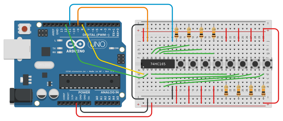
Now you can press those nice buttons and you will see their states via your serial monitor.
More shift registers
If you want to daisy-chain some shift registers, you only have to change a single number in your code. You have to change
ShiftIn<1> shift;
to
ShiftIn<2> shift;
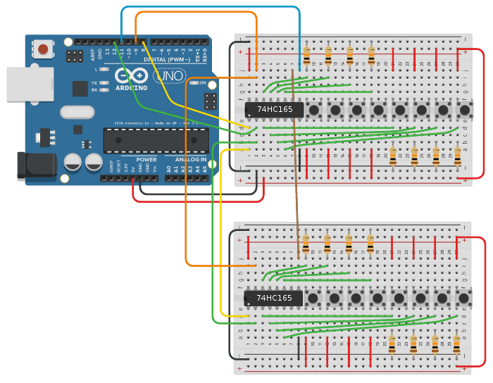
The second shift register is connected the same way as the first one. the only difference is the Q pin, instead of connecting it to your data pin, you connect it to the SER pin of your first register. If you plan to add more registers, you will connect the third Q pin to the SER pin of the second register, the fourth Q to the third SER, and so…
The breadboard layout for two registers will now look like this:
Thanks for reading!
I hope this little blog entry was useful to you! Have fun with my library :)