
As promised I will wire up a simple joystick this time. Furthermore I will give you a little overview over an Arduino joystick library.
Wiring
This time it is important to use an Arduino with an ATmega32u4 chip, like the micro. For testing purposes I just use two joysticks and 8 buttons. The buttons are connected via a shift register, while the joysticks are connected directly to an analog pin. For more info on the shift register, take a look at InfinityPi #3 or Arduino ShiftIn.
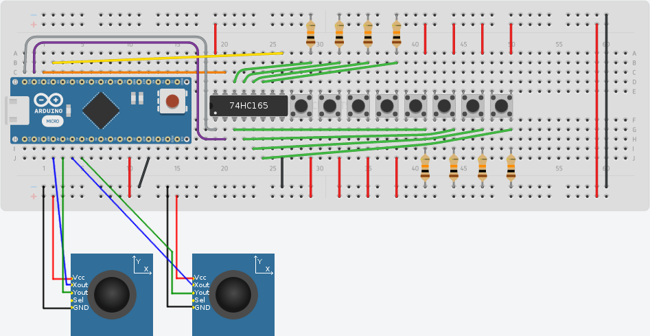
The pload pin of the shift register is connected to pin 12 (gray wire). The clockEnablePin is connected to pin 10 (orange wire). The dataPin is connected to pin 9 (yellow wire) and the clockPin is connected to pin 11 (purple wire).
The x- and y-pins of the joysticks are connected to the A0 to A3 pins.
Joystick Library
I use the joystick library (version 2) from MHeironimus. It is a nice little library that allows your Arduino to be recognized as a gamepad/joystick. The library can be found here: ArduinoJoystickLibrary. At the moment of writing the library is only in a beta state, but it works well. If the library is installed and included, you have to instantiate an instance of the Joystick_ class (the underscore is not a typo). After calling the begin function of this instance in your setup function, everything is ready to go. You can set your axis values by calling the setXAxis, setYAxis, … methods with a value between 0 and 1023 as a parameter. In order to press or release a button you could call setButton(idx, value) with a value of 0 or 1.
The basic code for my test gamepad is super easy:
#include <ShiftIn.h>
#include <Joystick.h>
ShiftIn<1> shift; // use one shift register
Joystick_ joystick;
void setup() {
  Serial.begin(9600);
  shift.begin(12, 10, 9, 11); // set pins of the shift register
  joystick.begin(); // init joystick
}

void loop() {
  // analogRead will read the axis value (0-1023)
  // set*Axis will set the axis value and automatically sends the change
  joystick.setXAxis(analogRead(A0));
  joystick.setYAxis(analogRead(A1));
  joystick.setRxAxis(analogRead(A2));
  joystick.setRyAxis(analogRead(A3));

  if (shift.update()) {
    for (int i = 0; i < shift.getDataWidth(); i++)
      joystick.setButton(i, shift.state(i)); // just press or release the button
  }
  delay(10);
}
After uploading this sktech to your Arduino, it will be recognized as a gamepad. Just go to your system control panel and take a look at the connected devices (on Windows 10, you could just open the menu and type “devices”). And there you will find this sweet icon:
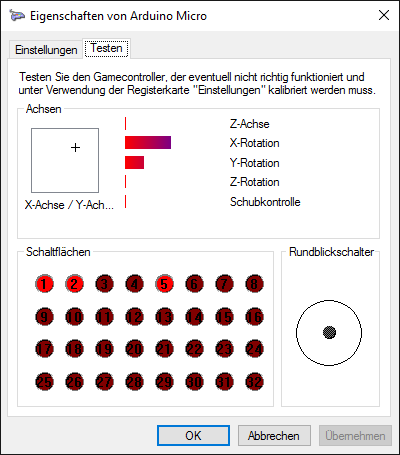
Now go to the controller settings and play a bit around:
To be continued
So basically we now have all gamepad parts together. The next big step awaits us: We have to build a small PCB for our buttons and we must of course implement the actual gamepad logic.
Furthermore it is time to think a bit about the triggers…